


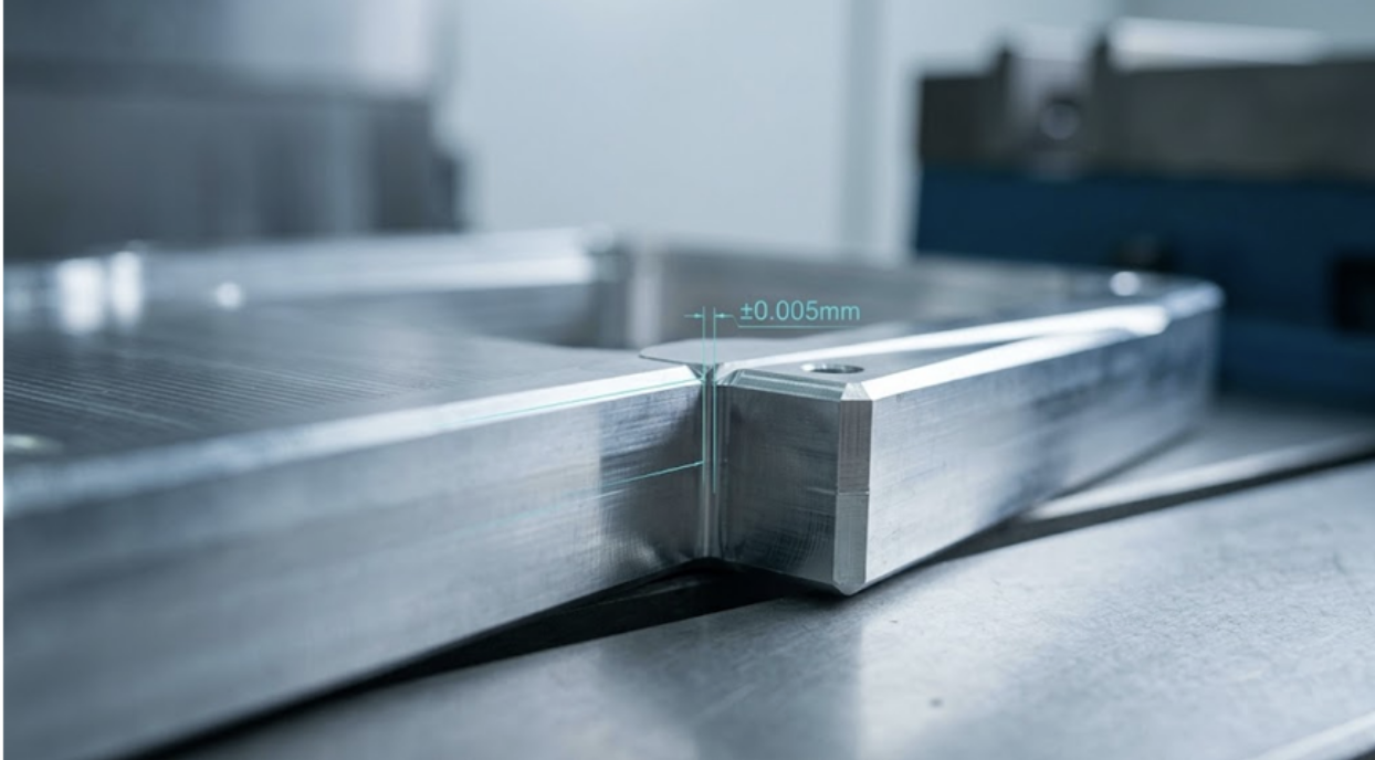
Engineering hardware products often fail during functional validation due to dimensional mismatch and thermal distortion. Ensuring assembly success requires balancing material properties, executing rigorous Design for Manufacturability (DFM) reviews, and utilizing multi-axis machining workflows to fabricate reliable Rapid Prototyping Parts before mass production begins.
Why Do Precision Hardware Prototypes Experience Severe Assembly Interference?
Assembly binding seldom originates from a single machined defect. It more often results from an accumulation of tolerance gradients in mating parts. If adjacent parts reach their minimum limits, they physically bind.Identifying these critical mistakes to avoid in prototyping early prevents costly engineering changes.
The Problem with 3D Tolerance Stacking
CAD models presuppose nominal geometry. Actual manufacturing gives tool deflection, thermal drift, and machine vibration. No consideration of multi-axis stack-up in initial modeling can result in extreme mechanical binding when fully assembled.
Material Stress and Asymmetric Deflection
Deformation of the thin-walled parts when unclamped. Residual internal stresses in raw rolled plates relax unevenly during material removal. When manufacturing prototype parts, teams have to take into account stress release using balanced part geometries and intermediate stress-relief operations to avoid scrap.
How Can Engineering Teams Select the Right Prototyping Pathway?
Evaluating different rapid prototyping processes requires balancing mechanical load, operating thermal range, and functional surface requirements. Structural metal components depend on uniform grain structures that additive methods cannot deliver.
| Evaluation Metric | Additive Manufacturing (3D Printing) | Sheet Metal Stamping / Forming | Precision CNC Milling & Turning |
| Material Density | Micro-porosity risks present | High rolled metal density | 100% wrought billet density |
| Tolerance Range | ±0.1 mm to ±0.3 mm | ±0.2 mm to ±0.5 mm | ±0.005 mm to ±0.01 mm |
| Surface Finish (Ra) | 3.2 to 6.3 µm (Post-process needed) | 1.6 to 3.2 µm | 0.4 to 0.8 µm (As-machined) |
| Structural Integrity | Anisotropic performance | High directional strength | Fully isotropic mechanical strength |
For parts that require exacting geometrical tolerances and genuine metallurgical characteristics, rapid prototyping cnc machining continues to be the accepted method of engineering. Subtractively machined parts behave in the same way mechanically as those produced by die-casting or forging further down the line.
What Pre-Machining DFM Rules Prevent Structural Defect Risks?
Addressing tooling limitations during CAD modeling prevents cutter deflection, chatter marks, and scrapped rapid prototyping cnc machining parts.
Internal Corner Radii Tuning
l No Sharp Edges: Iinternal square pockets increase the price as they require extra secondary EDM steps.
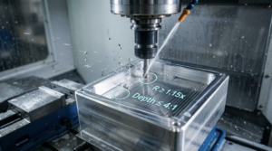
l Clearance of Cutting Tool:Ensure the internal vertical radius is larger than the radius of the cutter at least 15%.
Deep Pocket and Wall Thickness Ratios
l Uniform Wall Shape: Maintain the same cross-section thickness to remove the local thermal distortion.
l Depth-to-Width Limits: Maintain pocket depth-to-width ratio ≤4:1. Active multi-axis CNC milling illustrating critical DFM constraints for internal corner radii (R ≥ 1.15x) and cavity depth-to-width ratios (Depth ≤ 4:1).
How to Establish a Reliable Verification and Inspection Loop?
Precision hardware validation necessitates more than just the use of hand tools for coordinate metrology data. Precision geometries need coordinated physical testing procedures to ensure that the hardware fits functionally together.
The established quality inspection process has four steps of validation:
l Material Test Reports (MTR): Verification of metal alloy chemistry and its tensile yield strength.
l In-Process Probing: Detection of thermal and tooling drifts in roughing and finishing operations.
l Coordinate Measuring Machine (CMM) Inspection: True positioning of parts, surface profiling, flatness, and perpendicularity verification.
l Surface Profilometry: Surface roughness value quantification for O-ring grooves and dynamic bearings.
Partnering with dependable custom cnc machining services provides engineering teams with comprehensive first-article inspection (FAI) documentation, preventing dimensional variation across prototype revisions.
Why Does In-House Multi-Axis Capacity Protect Production Schedules?
Brokered manufacturing arrangements introduce communication lag, compromised intellectual property, and untracked subcontracting delays. Direct factory collaboration gives engineers transparent oversight across all rapid prototyping services.
Having direct connection with a manufacturing plant, for example JS Precision, having over 100 precision CNC machining equipment allows constant coordination on the technical front from the stage of analysis of CAD to parts delivery. In an environment of ISO 9001 quality management system, the direct manufacturing floor has control over the source of raw materials, fixturing, and coordinate measurement.
Conclusion
The predictable validation of prototypes necessitates DFM methodology, correct choice of manufacturing process, and closed-loop metrology. Taking care of geometric tolerance buildup and material stress at the initial stages prevents problems with budgeting and late assembly issues.
A DFM analysis by engineers needs to take place before releasing the tooling. Working directly with a reliable manufacturer such as JS Precision guarantees material compliance and CMM measuring.
Author Bio
Doris Wu
Precision manufacturing specialist supporting hardware projects from rapid prototyping to volume production, with core expertise in custom CNC, sheet metal, molding, and tight-tolerance DFM engineering.
FAQs
What gives CNC machining an advantage over 3D printing for functional metal prototypes?
CNC machining produces parts by cutting straight from billets of wrought metal, which eliminates porosity and reduces mechanical weaknesses. The result is actual tensile strength, fatigue resistance, and hermetic seals needed for testing.
How does uneven wall thickness cause structural deformation during machining?
Uneven forces acting on thin walls, along with the release of stresses, causes deflection that leads to warping and destroys concentricity of bearing bores and aligning surfaces.
Why is over-specifying tight tolerances detrimental to prototype development?
Too tight tolerances will necessitate slow grinding or EDM processes, increasing the time spent on setup and creating scrap parts, but not improving performance of the assembly.
Which verification data must appear in an engineering First Article Inspection report?
FAI document contains CMM measurements, GD&T of features, surface roughness, and material test reports, proving compliance with CAD requirements.
How can design teams optimize communication with machine shops to accelerate turnaround?
Provide clean 3D STEP files alongside 2D drawings that specify critical datums, thread standards, and surface finishes, allowing machinists to program toolpaths without clarification delays.

