


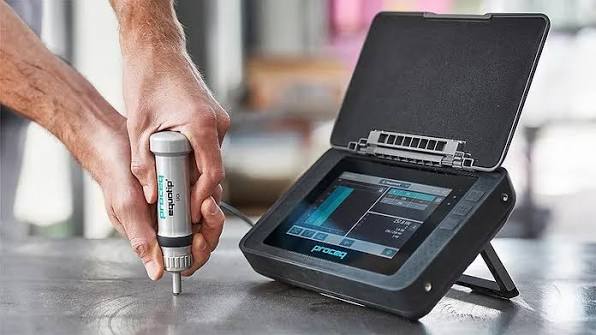
Spec sheets for hardness testers lead with force accuracy. A purchaser can check that figure; an auditor will ask about it, and it says almost nothing about how repeatable your Vickers results will be.
An operator measures the width of the mark left behind, and the formula does the rest. That puts the limiting step on a Vickers result in the optics and in the person at the eyepiece, not in the loading mechanism of the hardness testing equipment.
What the Vickers Number Is Computed From
ISO 6507-1 gives Vickers hardness as 0.1891 multiplied by the test force in newtons and divided by the square of the mean diagonal in millimetres. The indenter is a square-based diamond pyramid with a nominal face angle of 136 degrees, so the impression it leaves is a square, and both of its diagonals are measured. Clause 8.9 explicitly states that the arithmetical mean of the two readings shall be used in the calculation.
The squaring is the whole story, because an error entering at the measuring stage enters twice over, while the test force sits in the numerator once and unsquared.
Note 1 to clause 8.9 names the measuring step as the principal limitation. Low-force work suffers most.
Why Half a Micron Changes the Answer
Put a number on it. Writing in Advanced Materials and Processes, Vander Voort and Fowler measured how much operators vary when they re-measure an indentation they have already read, and found about half a micron for one person working alone and about a micron across several people.
Half a micron sounds like nothing until it reaches the denominator. On an indentation with a mean diagonal of ten microns, the same authors show a half-micron error moving the hardness value by roughly ten per cent.
An operator who habitually reads diagonals slightly short will bias a whole traverse upward.
A quality control manager signing off a traverse across a weld will not see that bias in the data, and no calibration certificate for the hardness testing equipment will surface it.
The Resolution the Standard Demands
Clause 6.3 ties the measuring device to the job in front of it, requiring a resolution that depends on the size of the smallest indentation to be measured. Table 3 then sets the figures.
Three things follow from that table, and the first is the one most often missed:
- A resolution of 0.0004 mm is required where the diagonal falls between 0.020 mm and 0.080 mm, which is four tenths of a micron on an impression of twenty to eighty microns
- Above 0.080 mm the requirement turns proportional, at 0.5 per cent of the diagonal, running up to 1.400 mm
- The table starts at 0.020 mm, so beneath a twenty micron diagonal the standard stops tabulating a resolution at all
Read those alongside the operator figures and a gap appears. The standard asks the instrument to resolve four tenths of a micron, while a single operator re-reading one indentation varies by about five tenths. The optics are held to a tighter figure than the person using them.
Keeping the Indentation Big Enough to Read
Vander Voort and Fowler recommend keeping diagonals above twenty microns wherever the work allows. The resolution table in ISO 6507-1 begins at the same figure. To get a diagonal that large, you raise the test force.
A Vickers hardness tester covers a wide span of forces, and the standard divides that span into three named ranges with hard boundaries at 49.03 N and 1.961 N. Above the higher figure, the test is the Vickers hardness test. Between the two, it becomes the low-force Vickers test, and below 1.961 N, down to 0.009807 N, it is Vickers microhardness.
ISO 6507-1 is candid about what happens as you work down that scale, noting that decreasing the test force increases the scatter of results.
You may not always be able to raise the force, though. A thin specimen, a plated coating, a case depth traverse and a weld heat-affected zone each put a ceiling on the force the geometry can carry, and the thickness rule in clause 7.3 is written in diagonals, requiring the test piece to be at least 1.5 times the indentation’s diagonal length. A larger impression needs more material underneath it, which those applications tend not to have.
Does a Lopsided Indentation Mean a Wrong Reading?
Often, yes. A square-based pyramid pressed squarely into a flat surface leaves a square impression, so two diagonals of noticeably different length indicate that something in the setup was not square.
ISO 6507-1 treats this as a measurable condition. On flat surfaces, the difference between the lengths of the diagonals should not be greater than 5 per cent, and clause 8.9 adds that where the difference is greater, this shall be stated in the test report. Clause 8.6 explains why by requiring the test force to be applied perpendicular to the surface.
An operator who notices a 7 per cent difference between the two diagonals has found a tilt problem, and has also acquired something that belongs on the certificate. The shape of the impression is a reportable fact about the mounting.
Frequently Asked Questions
What does HV 10 mean on a drawing?
The number is the test force, expressed in kilograms-force. HV 10 is therefore a test carried out at ten kilograms-force, which is 98.07 newtons and sits in the Vickers hardness range proper. A dwell time joins the designation only where a material’s time-dependent behaviour makes the standard duration unsuitable.
Why is the diagonal measured twice?
Because the impression has two of them. ISO 6507-1 requires measuring both diagonals of the square impression, and clause 8.9 requires using the arithmetical mean of the two readings in the calculation. The difference between them carries separate information about whether the surface sat perpendicular to the indenter.
Is Vickers more accurate than other hardness methods?
That depends on which part of the test you mean. You can apply and hold a force to tight specifications, but the result still depends on a diagonal reading to within a fraction of a micron, and ISO 6507-1 notes that the principal limitation is measuring those diagonals. Vickers accuracy rests largely on the measuring system and surface preparation, with the loading side of the hardness testing equipment held to its own separate specification.
How large should a Vickers indentation be?
Larger than twenty microns across the diagonal, wherever the specimen allows it. Vander Voort and Fowler recommend that floor, and the resolution table in ISO 6507-1 begins at a 0.020 mm diagonal. Beneath it the measuring step carries proportionally more of the result, whatever Vickers hardness tester produced the impression.
Does a tilted specimen have to go on the test report?
Yes, once the diagonals differ by more than 5 per cent. ISO 6507-1 states that, on a flat surface, the difference between the diagonal lengths should not exceed that, and that a greater difference shall be stated in the report. Clause 8.6 requires the force to be applied perpendicular to the surface, which is usually what a large difference points to.
What the Operator Contributes to the Number
A Vickers hardness tester holds its force to an auditable specification. The diagonal comes from the optics and from the person reading them. The formula squares that number.
Keeping indentations above twenty microns where the specimen permits, matching your measuring device’s resolution to the smallest diagonal the work will produce, and glancing at the gap between the two diagonals on every impression will between them account for most of the scatter you can actually control.
Across a shift, that habit shows up as narrower scatter on the certificate. For a laboratory reporting to several customers against several specifications, narrower scatter is what stops a result from being queried, and most of it is earned at the measuring end of the hardness testing equipment.

