


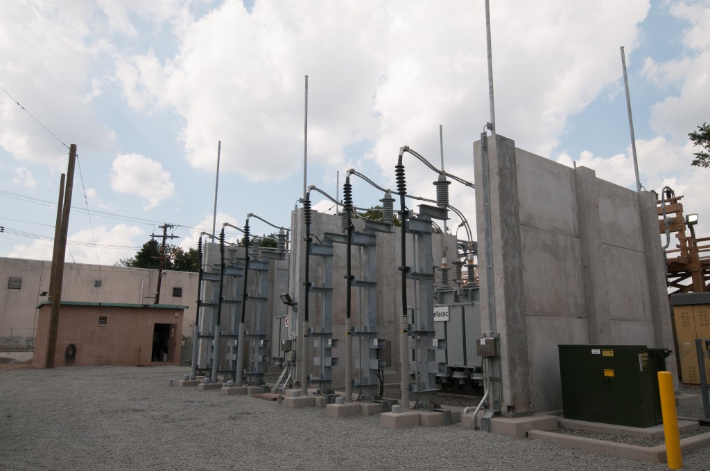
Utility and industrial substations face a concentrated mix of hazards around oil-filled transformers: internal arcing that ruptures tanks, projectiles from loosened radiators and bushings, and pool fires that radiate intense heat to neighboring assets. In greenfield sites, generous separation distances can limit the chance of domino failures. In built-up yards hemmed in by property lines, control buildings, and cable trenches, distance alone may not be possible. This article offers a practical decision framework for when a blast-rated barrier belongs in the layout, how it should interact with fire protection and containment systems, and what performance characteristics matter when the goal is to protect adjacent transformers, switchgear rooms, and critical control equipment.
-
The Events That Drive Barrier Decisions at Oil-Filled Transformers
The credible events that influence protective design differ from day-to-day operational risks. A sudden fault can cause rapid pressurization, sending tank fragments and shrapnel outward, while a spill-fed pool fire can expose neighboring equipment to sustained radiant heat. When separation is limited, a purpose-built Transformer Blast Wall can interrupt line of sight, absorb fragment energy, and reduce heat flux to adjacent transformers, cable trays, control houses, and relay rooms. Effective barriers are sized to shield vulnerable components like bushings and radiators and to account for debris projected by pressure relief devices.
Consider a constrained urban substation where a control building sits close to an oil-filled transformer and a ladder of overhead buswork runs above a cable trench. A tank rupture in that setting can send hot oil and splinters toward doors, louvers, and feeder entries. Even if a deluge system knocks down flames, radiant heat may crack windows and damage relay cabinets. This combination of exposure and limited standoff is a key signal that a blast-rated wall deserves serious evaluation.
-
Distance Versus Barriers in Tight Substations
Separation distance remains a proven control because it lets heat dissipate and debris fall short. But space is a finite resource. When property lines, right-of-way limits, and existing pipe racks box in a yard, pushing equipment farther apart can trigger land acquisition, permitting again, and duct-bank rerouting. A well-placed barrier provides immediate shielding without expanding the footprint. The tradeoff is complexity: walls require foundations, wind and seismic checks, and can affect firefighting water patterns. Where space is available, maintaining and inspecting distance is straightforward. Where it is not, a barrier can make compliance and risk reduction achievable without relocating major assets.
Picture a petrochemical plant substation where two main transformers back up to a busy pipe rack and a bank of cable trays feeding motor control centers. Adding a few feet of offset will not clear the exposure. A wall set between the transformer and the rack, with short return legs at each end, blocks direct flame impingement and prevents fragments from traveling toward the trays. The design must still preserve access aisles, crane clearances, and egress routes, but the barrier becomes the critical control that distance could not provide.
-
Loads, Materials, and Geometry a Blast-Rated Barrier Must Address
A credible barrier must handle combined actions: overpressure from a transformer fault, fragment impact from detached covers or radiators, and sustained thermal exposure from a pool fire. Reinforced concrete is common for its mass and heat resistance; modular systems using steel frames with cementitious or fiber-reinforced panels can speed installation in live yards. Height and width are geometry decisions with functional consequences: the wall should interrupt line of sight to critical targets like a control house louver or the adjacent transformer’s conservator, and end returns can prevent debris or flame “wrapping” around the edge. Foundations, anchor bolts, and embed plates must resist wall overturning under wind and seismic loads in addition to blast and thermal effects.
Placement details matter. Avoid locating a wall directly in the discharge path of a pressure relief device, where confinement can increase turbulence or redirect flame. Preserve transformer cooling airflow; some designs use offset gaps or elevated clearances to maintain convection while still blocking direct radiation. Protect steel components with coatings rated for hydrocarbon fire exposure. Where modular panels are used, confirm impact ratings for anticipated fragment velocities and provide spare panels onsite for rapid replacement after an incident. Small geometry changes, like extending a return leg or adding a parapet, often deliver large gains in protection.
-
Coordinating Walls with Deluge, Containment, and Electrical Safety
Barriers can interfere with water patterns from rim-mounted deluge rings, foam systems, or fixed monitors. Coordinate nozzle angles and monitor placements so spray reaches radiators and the tank body, not just the near face of the wall. Drainage must move burning liquid away from equipment. Tie the barrier layout to containment pits, curb heights, and trench drains so runoff flows toward oil-water separators rather than pooling at door thresholds. A common mistake is creating a heat “mirror” that reflects radiant energy onto the transformer or channels burning oil along a wall base toward a cable entry. Slope and curb details solve these problems before they appear.
Electrical safety integration is just as important. Bond metallic wall components to the substation ground grid to control touch and step potentials. Plan for lightning down conductors, and keep conductive loops out of inadvertent current paths. Place doors, gates, and removable panels so maintenance crews can rack out breakers, bring in test sets, and stage lifting equipment without breaching protected zones. Clear signage and painted keep-out lines help crews stay clear of the hazard side of the barrier during routine work.
A Practical Planning Sequence for Utilities and Industrial Sites
Start with a hazard assessment that defines credible events for each transformer: internal arcing, tank weld failure, bushing ejection, and pool fire scenarios. Map exposure targets, including control rooms, GIS buildings, cable trenches, neighboring transformers, and property lines. Use simple heat flux checks or modeling to test whether distance alone meets internal criteria and code expectations; add fragment trajectories and PRD discharge directions to the layout. Survey underground utilities and review geotechnical data to confirm foundation options. Then develop barrier geometry, materials, and returns that shield targets while preserving access, crane booms, and truck turning envelopes. Coordinate drawings with fire protection, environmental, structural, and electrical disciplines before finalizing submittals for the authority having jurisdiction and the insurer.
Commissioning and aftercare keep performance intact. Verify as-built clearances, barrier height, and return lengths. Confirm that deluge coverage reaches the tank and radiators and that containment drains freely to the separator. Add the wall to inspection rounds: look for concrete spalling, cracked grout pads, corrosion on embeds, and loose anchor bolts after storms or minor impacts. After any fire or pressure event, inspect for hairline cracking, panel deformation, or shifted supports and replace components as needed. Stocking spare modular panels or anchor hardware can turn a multi-week outage into a planned day of repairs.
Blast-rated barriers are not a cure-all, but in constrained substations and industrial yards they can decisively cut the chance that a transformer fault becomes a failure affecting multiple assets. The best outcomes come from early, cross-disciplinary planning: define the events that matter, compare distance to shielding, and make the wall part of an integrated design with deluge, containment, and grounding. With clear objectives and careful detailing, a thoughtfully placed barrier protects people, preserves critical power, and makes a challenging site layout work without expanding the fence line.

